Week 3 Lab
September 20, 2020
This is a blog post in a response to the third week assignment.
Analog Output and Input
Lab 1 was all about setting the stage for analog inputs.
Analog Input
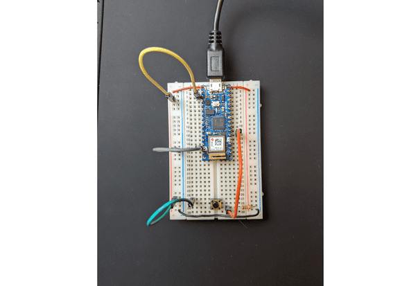
I first started with a standard button analog input. This was pretty straightforward. I also started dabbling in using my wirecutters to make my resistors flush with the board. I did end up ordering some wire to replace my jumper cables, and I’m looking forward to have a cleaner board!
Programming the Arduino
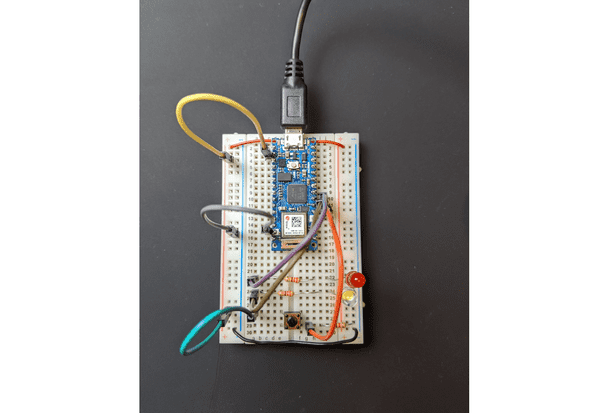
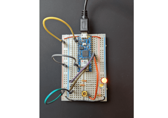
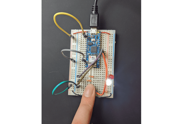
For this next part, I created a simple circuit using a button and two LEDs.
I did not have any issues with setting the Arduino IDE for this lab. I easily was able to upload and test with the nano. This was my code for the first part of the lab:
void setup() {
    // put your setup code here, to run once:
    pinMode(2, INPUT);
    pinMode(3, OUTPUT);
    pinMode(4, OUTPUT);
}

void loop() {
    // put your main code here, to run repeatedly:
    if (digitalRead(2) == HIGH){
        digitalWrite(3, HIGH);
        digitalWrite(4, LOW);
    }
    else{
        digitalWrite(3, LOW);
        digitalWrite(4, HIGH);
    }
}
With the resulting circuit:
Digital Input and Output
The second lab focused on digital input, meaning the input can have a spectrum and decimal values. I equate digital input like a “double” in programming.
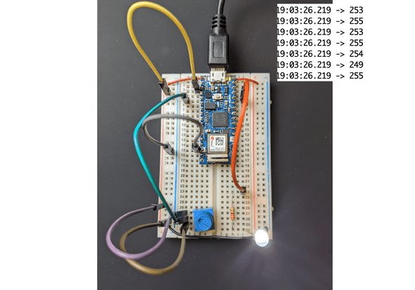
Potentiometer and LED
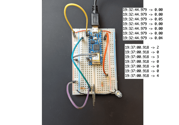
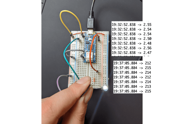
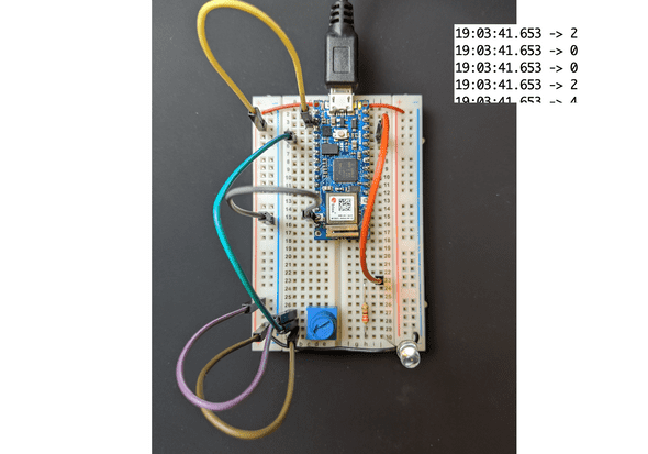
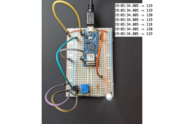
The first part of this exercise was using a potentiometer. In the code below, I print out the corresponding voltage for each measurement of the pontentiometer. There isn’t too much of a difference in the photos between halfway (120) and full (255) brightness, but in person it was clear.
const int ledPin = 9;
int analogValue = 0;
int brightness = 0;

void setup() {
    // put your setup code here, to run once:
    Serial.begin(9600);
    pinMode(ledPin, OUTPUT);
}

void loop() {
    // put your main code here, to run repeatedly:
    analogValue = analogRead(A0);
    brightness = analogValue / 4;
    analogWrite(ledPin, brightness);
    Serial.println(brightness);
}
Force-Sensing Resistors (FSR)
I had two parts to this:
Part 1 - Printing the Voltage
In the below code I printed the voltage for the pressure sensor.
void loop() {
    // put your main code here, to run repeatedly:
    int sensorValue = analogRead(A0);

    float voltage = sensorValue * (5.0 / 1023.0);
    Serial.println(voltage);

    analogWrite(9, brightness);
}
Part 2 - Printing the Brightness with Mapping
In the below code I printed the brightness, after mapping it to the corresponding values. I found the min and max by experimenting with the FSR and printing out the plain sensor value before trying to map it.
void loop() {
    // put your main code here, to run repeatedly:
    int sensorValue = analogRead(A0);

    int brightness = map(sensorValue, 0, 700, 0, 255);
    Serial.println(brightness);

    analogWrite(9, brightness);
}And that’s that!
a blog by sam heckle class of itp 2022. doing shit. twitter.
